gas-turbine engine dynamic response analysis through simulation
M.K. Leontiev, E.V. Borsdyko, S.L. Zvonarev, Aircraft Engine Department,
Moscow Aviation Institute
- Abstract
- Introduction
- Principal Stages of GTE Vibration Analysis
- Engine Models and their Identification
- Analysis of Rotor Critical Speeds and Mode Shapes
- Analysis of Forced Vibrations of GTE Linear Dynamic Systems
- Squeeze-Film Damper Design
- Forced Vibrations of the GTE Nonlinear Dynamic System
- Conclusion
- References
Abstract
The authors, being well-experienced in the development and application of software in the dynamic response analysis for complex rotor systems, consider specific phases in the work of designers, who use the software in the process of design and bringing to perfection multi-shaft turbine engines.
Under consideration are methods of preparation and identification of engine models, rotor critical speed and mode shapes analysis through distribution of strain and kinetic energy, as well as an analysis of forced vibration from unbalance system both in linear and in nonlinear statements. Designing of turbine engine structures with nonlinear squeeze film damper supports are also considered.
The results of research of the ship three-shaft turbine engine are given as an example.
Introduction
Creation of high-reliable as to vibration-proof characteristics of gas-turbine engine (GTE) structures is one of the most important aspects in modern engine manufacturing. One of the ways of its solving is the application of mathematical simulation technique of the engine dynamic response in every stage of its design, development and operation.
At present the problem of mathematical simulation effective technique and software creation has been paid great attention to by many scientists and engineers. Among fundamental works of GTE analysis technique development as a complex dynamic system the works of Bohm [1], Ivanov [2], Hibner [3], Childs [4], Gunter [5], and a number of other authors can be emphasized.
Moscow Aviation Institute has been developing mathematical simulation complex means and technique for many years, which surpass experimental studies in speed and providing data though negligibly yielding to them in the body of the problems solved and the results accuracy, i.e. a certain mathematical stand is being created where GTE vibrations studies can be conducted in a full volume. Such a stand is a "DYNAMICS" interactive software system.
The system solves the following basic problems (in brackets the applied software technique is pointed out):
- computer-aided development of analytical models complex rotor systems ( CAD methods);
-critical speeds and mode shapes analysis (transfer matrix method for multilevel beam systems);
- distribution analysis of strain and kinetic energy of rotor system vibration by the elements of mode shape proper;
- forced response analysis of the engine linear dynamic system at nonsynchronous excitation from a distributed unbalance system, arbitrary external force and ground motion (modal analysis and synthesis methods for decreasing dimensional representation of the problem);
- forced response analysis of nonlinear rotor systems (modal analysis and synthesis methods, transient analysis, Fast Fourier Transform analysis. Nonlinear elements - supports squeeze-film dampers of different types, hydrodynamic bearings, rolling bearings, etc.);
- special problem solution - blade loss, rotor rubs, etc.
In known papers and reports the questions of developed technique and GTE structures dynamic response analysis software from the point of view of an engineer designing an engine and bringing it to perfection are seldom considered. Together with this the problem by itself is as important as development of new mathematical models. The authors have made an attempt to set concrete stages in the designer work with the similar software.
As an example the results of a ship gas-turbine engine have been used, Fig.1
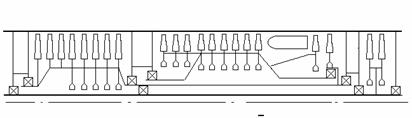
Fig 1. Ship Three-Shaft Turbine Engine
Principal Stages of GTE Vibration Analysis
During the GTE dynamics systems study the following principal stages can be pointed out:
- Data preparations on the engine model, the engine model identification by the experimental data obtained. The objective of the stage is to construct a design model ready "to predict" a GTE dynamic response.
- Analysis of rotor critical speed and mode shapes of the engine dynamics system. Distribution analysis of strain and kinetic energy by the structure elements. The particular GTE structure elements effect (e.g. rotor supports) on resonance zones. The objective of stage is to determine the most dangerous resonance regimes within the operating range, choice of places for dampers, flexible elements, accelerometers to be mounted.
- Analysis of amplitudes of response from single unbalance with account of distribute structure damping. The objective of the stage is the quantitative evaluation of a vibration level in the system of the engine. The final feasibility grounds of dampers and flexible elements to be mounted.
- Analysis of amplitudes of response from the GTE distributed rotor unbalance system. Determination of vibration speeds in the places of accelerometers installation, the level of load of rotor supports, rotor relative displacements depending on stiffness of supports and damping in them. The objective of the stage is a more definite quantitative evaluation of amplitudes of response, determination of desired dynamic characteristic of rotor supports.
- Analysis of dynamic characteristics of different types of flexible damping supports. Choice of structure parameters of supports with a high degree of characteristics linearity. Design of dampers, analysis of GTE nonlinear system dynamic response with "normal" unbalance distribution and their higher value for every critical point of the structure and a regime. The objective of the stage is to evaluate the structure normal operation and to design an optimum GTE dynamic system.
- Solution of special problems. The objective is to study and predict the GTE dynamic response in possible operational conditions. Here the problems associated with, for example, nonstationary modes due to blade loss, aircraft rough landing, rotor rubs, etc. can be solved.
The considered division into stages under the GTE dynamic response study through mathematical simulation technique is rather arbitrary. Together with this the division substantially represents a minimum set of problems of GTE general dynamics necessary to be solved in designing any engine.
Engine Models and their Identification
A problem of developing dynamic engine model is the most responsible stage in the work of a designer. Three basic phases of change over from the structure to an engine model can be differentiated.
- A principal model. Here subsystems, each representing one of the functional or structure elements, are defined. The subsystems are interconnected by flexible lateral connections.
- An idealized structure model. At this phase all the subsystems are divided into sections, each of them can be described by a standard element, for which there are analytical dependencies of its mass and flexible characteristics design.
- An spring-mass model. At this phase every section of an idealized model is reduced to a common form - a linear massless section with concentrated mass elements at its ends. Such sections form a spring-mass model. Fig.2 shows a spring-mass model of the engine under study with particular cross sections.
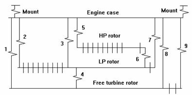
Fig 2. Line Diagram for Engine Model
After determining a engine model by a designer a problem of setting its similarity to a real structure is to be solved - i.e. an identification problem. Since the type of an engine model and its structure are known beforehand, the identification problem reduces to definition of the values of some parameters or functional dependencies making it more definite [6].
With the aim of reducing labour of an identification problem of GTE models the authors of this paper apply a rather simple method allowing obtaining good results.
Identification is carried out by stages and comprises the following types of work.
Statical Identification. The basis is engine model redetermination by its flexible characteristics. The experimental data for performing this identification are loads and structure strain under their effect. While identifying theoretical and experimental deflection lines due to corresponding loads effect are compared. Certain correlation coefficients with a physical sense of local coefficients of flexibility can be introduced into consideration, the best comparison can be obtained by their varying.
Frequency spectra identification. After the performed statical identification the comparison of frequency spectra of a real structure obtained in experiments as a result of a harmonic analysis is conducted with an analytical results. The main structure elements by which the engine model identification is performed are rotor supports, by varying stiffness of which we can change the position of corresponding rotor critical speed. The purpose of this identification is given by the information of energy distribution by structure elements at corresponding mode shape.
Analysis of Rotor Critical Speeds and Mode Shapes
In a general case it is necessary to analyze critical speeds and mode shapes for each rotor of engine [8], however, for some engines rotor spectra can slightly differ between themselves. This allows to apply only one spectrum for analysis, for example, of a high pressure rotor of a maximum critical speeds.
Table 1 represents critical speeds of high pressure rotors and lateral mode shapes of the engine dynamic system. Let's analyze these mode shapes using distribution of strain and kinetic energy by the system elements.
Point out first that in this version of an engine dampers are absent. There are flexible nonlinear elements of "a squirrel wheel" type with displacement restriction, designed for changing-over via resonance zone, in the support joints of the rotors (connections 2 and 5).
- Mode - 3636 rpm. Kinetic energy distribution of vibrations shows the high pressure rotor to be the main exciter of this mode shape. The forward support of the high pressure rotor (connections 5), where "a squirrel wheel" is installed accounts for 22% of strain energy. In the case of gap section disappearance the support stiffness increases and the mode shape shifts upwards by rotations. This mechanism of control allows to pass a resonance zone corresponding to this mode shape without increased vibrations.
- Mode - 5129 RPM. This mode shape can be excited by both a high pressure rotor and a low pressure rotor. The mode shape control is carried out by nonlinear flexible elements.
- Mode - 6198 RPM. This mode shape is similar to the previous one. The mode shape control is carried out by nonlinear flexible elements.
- Mode - 10510 RPM. The first bending mode shape of the screw rotor. Due to the fact that the mode shape is beyond the operating rotations of the screw rotor , a high pressure rotor and a low pressure rotor not storing up kinetic energy, it is not excited.
- Mode - 14485 RPM. The shape is beyond the limits of operating rotations of a low pressure rotor and a screw rotor but lower than the maximum rotations of a high pressure rotor. The case accounts for 57% of strain energy, which shows its substantial strains. A considerable share of high pressure rotor kinetic energy (more than 16%) shows the mode shape to excite with its frequency.
- Mode - 16768 RPM. The second bending mode shape of the screw rotor. It is rather far behind the operating rotations of the rotor and its control may not be carried out.
The shape control can be carried out with the help of a damper. Strain energy distribution by connections shows an exact place of damper mount - a back support of the low pressure turbine rotor storing up more than 13% of strain energy.
Analysis of Forced Vibrations of GTE Linear Dynamic Systems.
The computation of force vibrations allows to give a quantitative evaluation of engine dynamic response. It can be performed both from separate unbalance defining the level of vibrations at synchronous regimes, which is rather useful for solving an identification problem, and a distributed unbalance system by every rotor which gives an opportunity to take into account the interaction of rotors and to obtain nonsynchronous vibrating components.
For the engine under study initially forced vibrations with excitation from each separate rotor in the place of accelerometer installation were calculated. The calculation supported the previously made conclusions - maximum vibrations appear with the high pressure rotor frequency being 14500 RPM, Fig.3. The same regime was observed in the experiments as well.
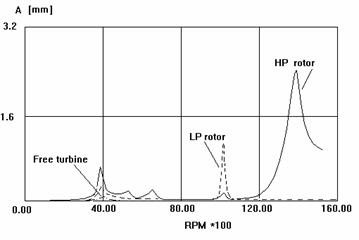
Fig 3 Synchronous Forced Response of Linear Model
A more accurate qualitative evaluation of forced vibrations has been computed with account of a distributed unbalance system of the whole engine. Fig.4 represents the obtained dynamic response characteristics by both a general level of vibration and its components. These diagrams show the experimentally obtained characteristics as well. The general level of vibrations within the engine operating range is seen to considerably exceed the values of allowable limits and changes are to be introduced into the structure.
Such a change is a damper mount into the low pressure rotor turbine support.
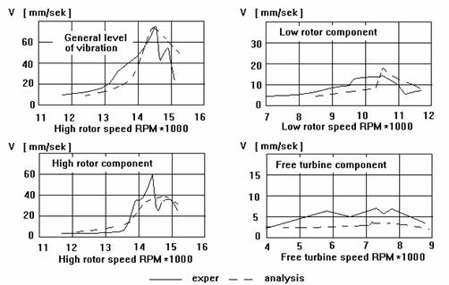
Fig.4 Dynamic Response Characteristics of Linear Model
Squeeze-Film Damper Design
One of the common methods to select geometrical dimensions - a gap, length, a squeeze-film damper diameter is utilizing some generalized semi-empirical criteria permitting to evaluate damper effectiveness, e.g., the one as in Ref.[7].
The basis of the damper design method applied here is the use of linear models of GTE dynamic system and dampers of different structures with the following engine dynamic response estimation in a nonlinear transient analysis. Such an approach enables to get desirable time of designing and good practical results. The design process supposes separate design of dampers with tuning each of them to a certain resonance regime connected with the excitation from one of the rotors.
At the first phase a parameter study of support stiffness effect and damping is carried out where a damper will be mounted at the level of vibrations by different criteria, a field of possible values of stiffness and damper characteristics being set up as a result. This approach is also used in Ref.[8].
At the second phase a selection of a chosen damper structure according to the required engine rotor system dynamic characteristics is performed. The damper characteristics analysis is done independently in supposition of rotor circle precessions (Fig 5). The final check of the damper operation is carried out in nonlinear analysis of the engine dynamic systems.
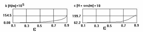
Fig. 5 Stiffness and Damping Coefficicients
Forced Vibrations of the GTE Nonlinear Dynamic System
The dynamic response nonlinear analysis should be conducted with account of gravity and distributed unbalance system.
By the data obtained the amplitudes of response have been constructed both by a general level of vibration and the components with frequencies of all the rotors, Fig.6. The comparison shows good convergence of analytical results with the experimental ones. As in the experiment a vibration component with a low pressure rotor frequency makes the major contribution.
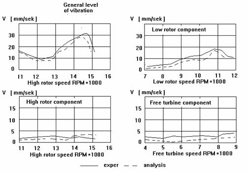
Fig. 6 Dynamic Response Characteristics of Nonlinear Engine Model
In calculating nonlinear dynamic systems by approximated methods the accuracy issues take a particular place, the researcher still being directly responsible for taking care of them. Here the following remarks can be made.
In applying modal methods of analysis and synthesis as a basis it is necessary to use a set of mode shape obtained under minimum stiffness of nonlinear structure elements from the range of their changes.
The truncation frequency is to be set by three, four times higher then maximum rotor speed.
And, at last the moment of obtaining a decision in the transient analysis can estimated by the set orbits of the rotors relative motion in the gaps.
Conclusion
The authors have applied not a single formula in the paper believing the applied mathematical methods to be well known and utilized in research practice of different rotor systems. Alongside with this there remains a problem of perfecting mathematical models of dynamic systems of complex rotor systems and the designer practical means created on their basis. We see the following problems still be solved.
- Development of models and software for the study of connected lateral, axial and torsional vibrations.
- Perfecting the models of accounting structure friction in the cases and rotors.
- Development of aerodynamic excitation account models.
- Perfecting the methods of engine models preparation and their identification.
- Creation of modern means of vibration diagnostics on the basis of developed research software of GTE dynamic response.
References
- Bohm,T. Tame The Menace of Turbine Vibration, SAE Journal, February 1966, pp.44-48
- Ivanov,A.V. Computing of GTE Resonance Regimes, Trans. Moscow Aviation Institute, V.245, 1972, pp. 66-77.
- Hibner,H. Dynamic Response of Viscous-Damped Multi-Shaft Jet Engines, AIAA J.Aircraft,Vol.12, No.4, 1975, pp.305-312.
- Childs,D.W. A Modal Transient Rotor-Dynamic Model for Dual-Rotor Jet Engine Systems, Journal of Engineering for Industry. Trans.ASME, August 1976, pp.876-882.
- Gunter,E.J.,Li,D.F. Component Mode Synthesis of Large Rotor Systems, Trans.ASME, Vol.104, Jule 1982, pp.552-560.
- Marmol,A.A.,Akin,J.T. Rapid Verification of Engine Rotor Case Flexibilities by the Modal Comparison Algorithm, Journal Aircraft, Vol.12. No.4 1975.
- Mohan,S.Hahn,E.J. Design of Squeeze-Film Damper Supports for Rigid Rotors, Journal of Engineering for Industry, Trans.ASME, August 1974, pp.976-982.
- Bhat,S.T.,Buono,D.F.,Hibner,D.H Analysis of High Load Dampers, NASA-CR-165503, Final Report, 1981, pp.79.