3.3.2 Flexible element analysis
The flexible element layout and calculating scheme is shown in Fig 12.
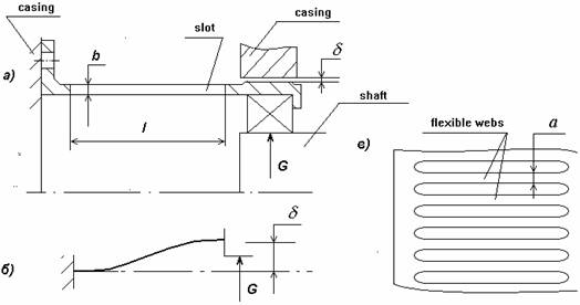
Fig 12 . A “squirrel-weel” type flexible element.
a) design scheme and main dimensions; b) loaded bar displacements; c) cylinder involute view
An FE stiffness can be calculated by
![]() ,
,
where
n - number of bars;
a, b, l - width, thickness and length of a bar accordingly;
E - Young module of the bar material at operating temperature.
 - correction coefficient, depending on the flexible
web dimensions
Maximal alterating stress in the bar ,
,
where ; n = 0 or 1
d - radial clearance
Static displacement under the support weight G loading
d0 = G/K .
Static stress in a bar under the weight loading
![]() .
.
To balance the weight displacement as to center the bearing its initial location is to be preliminary moved d0 upwards.
Fatigue margin is determined by dynamic sa and static sm stresses
![]() ,
,
where
![]() - fatigue limit of a flat coupon;
- fatigue limit of a flat coupon;
s-1 - - fatigue limit of a standard circle coupon;
ys - material sensitivity to the fatigue cycle non-symmetry;
![]() - fatigue resistance coefficient;
- fatigue resistance coefficient;
ks - effecttive stress concentration;
![]() - surface state coefficient;
- surface state coefficient;
![]() - scaling factor.
- scaling factor.
Sometimes fatigue and stiffness requirements contradict each other. If so a "two-stores" design can be recommended which is a support furnished with two co-axial “squirrel-cages”.
![]()
![]()
![]()